Final Robot Design
CAD and Mechanical Design
Mechanical Design Overview:
- Custom Laser-cut Chassis
- Custom 3D Printed Wheels
- Drivetrain with indepent 5V power supply
- Faster Continous Rotation Servos
- Time of Flight Wall Sensors via I2C
- Power Distribution/ I2C Proto Board
- Treasure Sensor Amplifier Protoboard with singaling LEDs
- Embedded Microphone
- Treasure Sensor Adjustable Extension Arms
- Dedicated FFT Arduino
- Optimized wiring, no breadboards
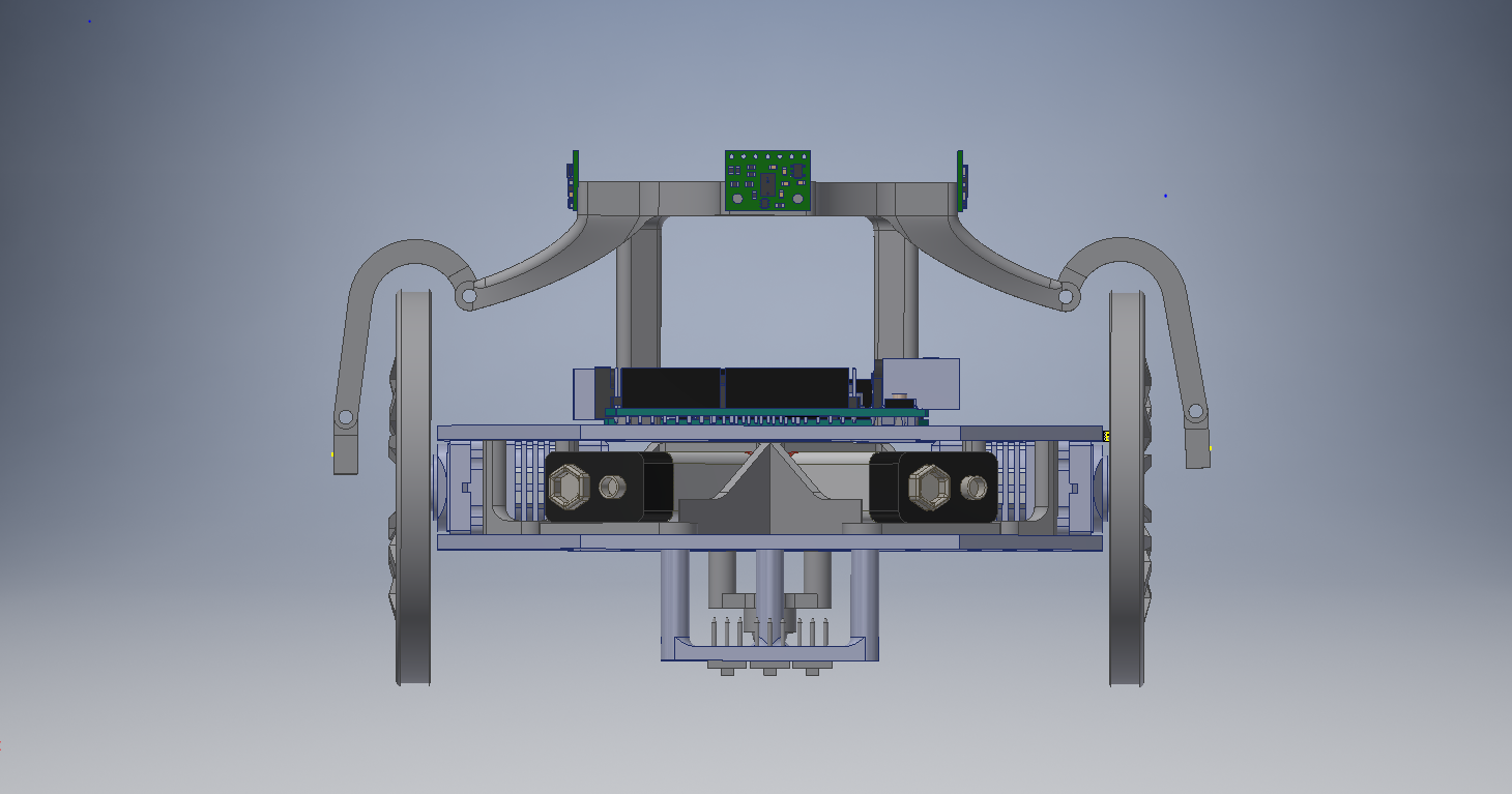
The entire robot was CADed using Autodesk Inventor Professional CAD software. Below is a picture of the final robot CAD.
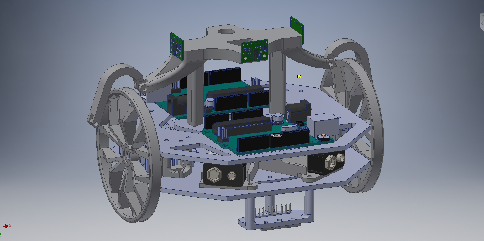
The first step is designing a cutom robot where to choose a new chassis and drivetrain. For the chassis frame, we dicided to use a symmetric hexagonal shape, to accomodate for the the orthogonal symmetery of the maze structure. The intention was to design a robot that was a long as it was wide considringt the robot would have to make 90 and 180 degree turns ina confiened maze width. Next for our drivetrain, we knew we wanted a fast robot, which meant faster servos/acutarors or larger wheels. Orginially, we 3D pritned large, lightwerigth cusotm wheels for the original servos. Eventually we bought high speed continuos rotation servos, whic had 3x the top RPM as the original servos. After having linefollwoing code with the old servos, when switching to the fast servos line following became very difficulto to tune due to the lwo resolution of the servo speed. Essentially, the servos combined with the large wheels were to fast and thr obot would overreact and move off the line. In the end we stuck with our orignial servos and the large wheels, in order to not have to deal more servo control resolution. Custom 3D printed servo mounts were used to fix the servos between two laser0cutt chassis plates.
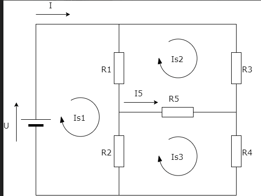
Once we had a custom chassis down, we created an indepent power supply for the driveline using a 9V battery and 5V linear regulator. This was necessary because throughout the first few labs we had a recurring issue of the Arduino restarting in the middle of its movement. We later deduced this was due to high back-emfs caused by the servo’s quick accelerations. By providing the servos with a power supply indepentent of the Arduino’s, the voltage spike cannot cause the Arduino to restart. As a result, we used the following circuit to establish an independent power supply for our drivetrain.
After seeing the poor quality and performance of the mid-range IR sensors for wall detection, we chose to buy more accurate sensors. The original IR sensors outputted analog values whose range was not directly proportional to the distance. In fact, two different ranges could output the same analog value. For this reason as well as our limited number of analog input pins, we choose the VL6180X Time of Flight Distance Ranging Sensor for wall detection. These sensors resulted in much higher accuracy and freed up analog pins for treasure detection and line following. We 3D printed a mount to hold all three ranging sensors above the plane of the wheels 90 degrees apart. This sensor stand was specially designed for integration of the wall sensors, IR sensors, microphone, and power distribution and IR amplifier protoboards. The stand has a pocket for the microphone to be embedded above all other sensors to easily hear the starting tone. It also has arms that extend below the wall sensors to hold the IR photodiodes used for treasure detection as close to the walls as possible without falsely triggering the wall sensors. Finally, the stand was supported by two posts, which had rails in them to hold protoboards for I2C, power distribution, and treasure sensors amplification. The treause sensor extension arms were designed to place the IR photodiodes at the same height as other treasures, 4cm above the ground. Additionally the extension arms are able to pivot to properly align the IR sensors to face the treasure.
Our robot used two Arduinos, one which ran the drivetrain, line follwoing, and DFS algortihm, and the other which detected treasures and the starting tone via FFT analysis on sensor inputs. This was done because we were warned that the FFT library we used in lab to distinguish between sound tones and treasure frequencies was causing bugs in working code once intregrated with other code such as line following. This was partially due to the the fact the interupts were turend off and pwm signals were distorted in the FFT library.
Finally, in order to minimze wiring confusion or failure due to bad wiring connections, we elimnated all breadboards and jumper cables. All circuits on the roboy with the exception of the IR photodiodes are permanently soldered. A protoboard was created in order to distribue power to all sensors on the sensors stand, including the IR photodiodes, microphone, and wall sensors, as well as host the I2C bus SDA and SCL lines. Another protobaord was used for the amplifier ciruit that enabled treasure to be detected up to 4 inches away. Both of these protoboards were installed vertically directly into the stand rails so as to minimize wire length.
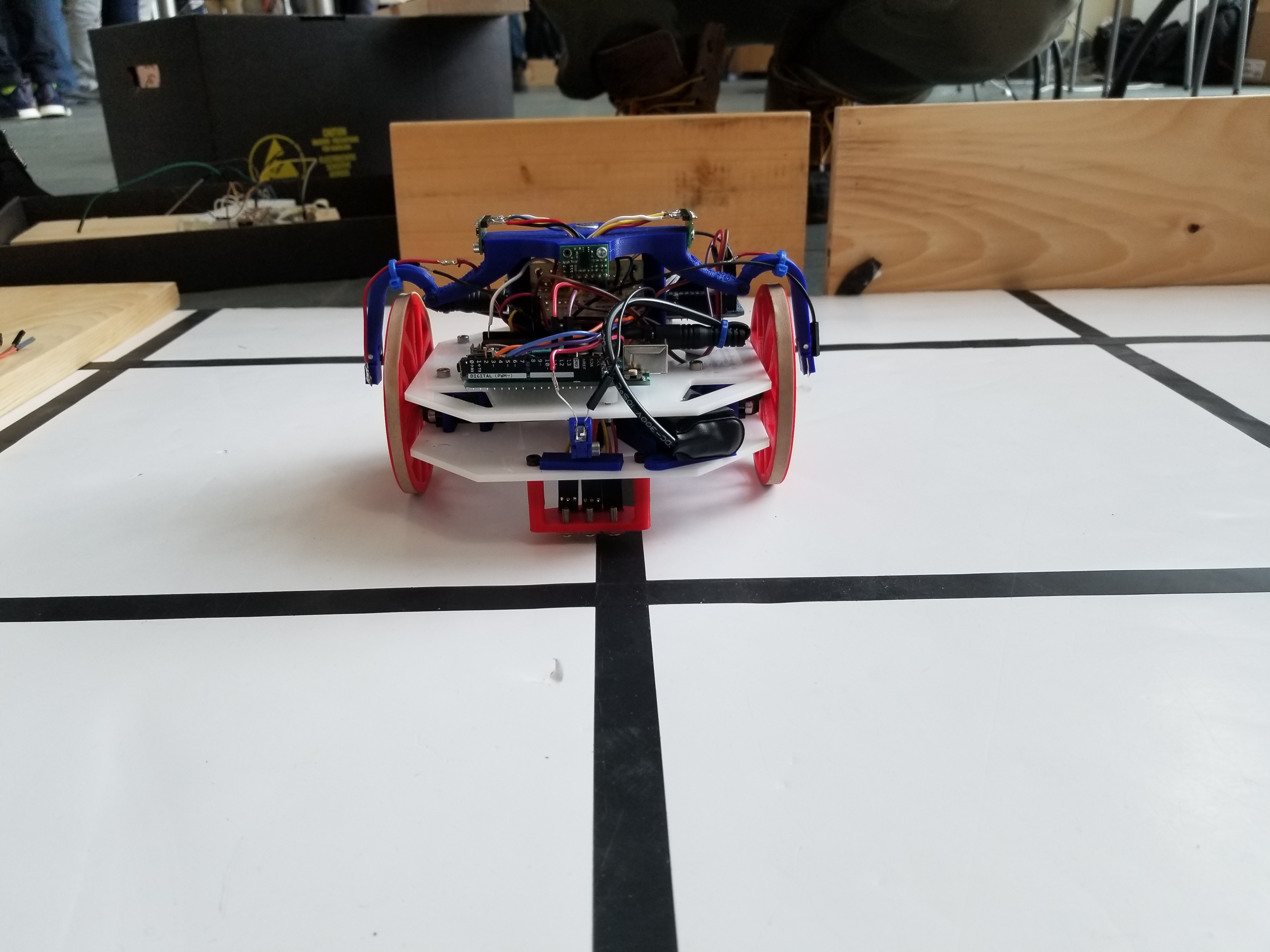
Line Following
Even though we had three line sensors on our final robot design, our line following algorithm only really used two of them. The sensors we used were the provided line sensors we got in Lab 1, and we read their values using analogRead(). The plan was to move the third back to be inline with the middle of the robot in order to allow us to stop exactly on intersections without using millis(). The line sensing algorithm for following a straight line was extremely basic, and we implemented it using an FSM with the following states: STRAIGHT, SLIGHT_RIGHT, SLIGHT_LEFT, RIGHT, LEFT, INTERSECTION, TURN_AROUND. For example while the right sensor’s value was above the threshold (higher value -> darker), the robot moved the right servo slightly faster, and the left servo slightly slower (that’s the SLIGHT_LEFT state). This moved the robot back onto the line and was far smoother than having one wheel stop completely, or running the wheels in opposite directions. At an intersection, signaled by both of the line sensors being on a line, the robot would continue forward an amount of time based on the speed of the servos, and then stop in the middle of the intersection. If the robot stopped as soon as it detected an intersection, the robot would actually be behind the intersection, which would hinder turning and cripple treasure detection. Below is a picture of our final robot design, note the three line sensors in the front. The center line sensor is the one we don’t use.
Wall Detection
Initially we were using the provided wall sensors, however since we had three wall sensors on our robot, that used up three possible inputs to our ADC, which we needed for other things. To free up pins on the ADC, and in order to get more accurate wall sensing, we ordered three VL6180X time-of-flight($11.95 x 3 = $35.85 cost). sensors from Pololu. These sensors used i2c to communicate, and were more complex to set up than our previous sensors. However the gains in accuracy, stability and free ADC ports were worth it. We had a mysterious bug where our robot’s processor would deadlock seemingly randomly, attemps to debug the issue were fruitless, until we learned that the Arduino Uno’s built-in i2c SCL and SDA lines were actually tied to analog pins A4 and A5, which we were using. This was causing the crashing behavior. Once we freed up A4 and A5, the wall sensors worked wonderfully, however since we couldn’t use A4 and A5, our net gain was only one analog pin. Eventually we moved to an Arduino Mega so we could have more Analog pins, however we ended up moving treasure and sound detection to a separate Arduino so we actually ended up not needing the extra pins the Mega offered.
Maze-Solving Algorithm
First of all, we would like to clarify that our movement algorithm, meaning servos combinations to help our robot move, was the same as in previous milestones. It was a simple variable of type State that would indicate the robot where to go, including LEFT, RIGHT, STRAIGHT, etc. When deciding to implement a maze-solving algorithm, we considered the different available options and how they could benefit and work with the capabilities of our robot. After some research on efficiency of movement and mapping, and the fact that the robot was supposed to map a considerably small maze, we decided to go with Depth-First Search. This algortihm was not only supposed to provide a very straight forward movement sequence based on putting possible “paths” on the stack -always prioritizing the forward movement-, but it would also indicate that our robot was done mapping the maze by emptying the stack and having no more unvisited intersections to go. We used the
enum Orientation{
  NORTH,
  SOUTH,
  WEST,
  EAST
};
Given these possible orientations, we were able to easily convert wall detection from robot to maze perspective:
void wallMaze () {

  // Initializing array to all false
  for (int i = 0; i < 4; i++) {
    actualWalls[i] = false;
  }

  // The output of this function is described as left-up-right-down
  if (walls[0] == true) {
    switch(robotOrient) {
      case NORTH:
        actualWalls[0] = true;
          break;
      case EAST:
        actualWalls[1] = true;
        break;
      case SOUTH:
        actualWalls[2] = true;
        break;
      case WEST:
        actualWalls[3] = true;
        break;
    }
  }

  if (walls[1] == true) {
    switch(robotOrient) {
      case WEST:
        actualWalls[0] = true;
        break;
      case NORTH:
        actualWalls[1] = true;
        break;
      case EAST:
        actualWalls[2] = true;
        break;
      case SOUTH:
        actualWalls[3] = true;
        break;
    }
  }

  if (walls[2] == true) {
    switch(robotOrient) {
      case SOUTH:
        actualWalls[0] = true;
        break;
      case WEST:
        actualWalls[1] = true;
        break;
      case NORTH:
        actualWalls[2] = true;
        break;
      case EAST:
        actualWalls[3] = true;
        break;
     }
  }
}
With actual walls taken care of, we had to use robot-perspective wall detection and orientation to update the stack appropriately with the possible paths:
void updateStack(){

  // Pushing possible paths into the stack
  switch(robotOrient){
    case NORTH:
      if(walls[0] == false) { stack.push(inters[current_pos_x][current_pos_y - 1]); }
      if(walls[2] == false) { stack.push(inters[current_pos_x][current_pos_y + 1]); }
      if(walls[1] == false) { stack.push(inters[current_pos_x - 1][current_pos_y]); }
      break;
    case EAST:
      if(walls[0] == false) { stack.push(inters[current_pos_x - 1][current_pos_y]); }
      if(walls[2] == false) { stack.push(inters[current_pos_x + 1][current_pos_y]); }
      if(walls[1] == false) { stack.push(inters[current_pos_x][current_pos_y + 1]); }
      break;
    case SOUTH:
      if(walls[0] == false) { stack.push(inters[current_pos_x][current_pos_y + 1]); }
      if(walls[2] == false) { stack.push(inters[current_pos_x][current_pos_y - 1]); }
      if(walls[1] == false) { stack.push(inters[current_pos_x + 1][current_pos_y]); }
      break;
    case WEST:
      if(walls[0] == false) { stack.push(inters[current_pos_x + 1][current_pos_y]); }
      if(walls[2] == false) { stack.push(inters[current_pos_x - 1][current_pos_y]); }
      if(walls[1] == false) { stack.push(inters[current_pos_x][current_pos_y - 1]); }
      break;
  }
}
With a valid stack, we were left with a very important aspect of maze-solving: back-tracking. Sadly, after spending a lot of time of this algorithm, it was constantly encountering new and more devastating bugs every time, therefore it did not perform properly at Competition Day. We based this algorithm as a simple loop condition that would be trigerred once true: if the position you want to go is at a distance greater than 1 intersection -either in the x or the y axis-, start back-tracking. We made this possible by creating a struct inters for every intersection that would hold the previous intersection the robot visited before getting there. Additionally, we checked that in the case of having our to-go intersection at a reachable distance of 1, we also checked for walls to avoid crashing. Although it could not get it done sometimes, we definitely experienced previous mappings where the robot behaved as intended. However, the only times it failed, it was because of erroneous back-pointer analysis, since we did some solid testing on the stack implementation.
Treasure Detection and Start Tone Detection
After Lab 2, we were able to detect treasure from a little over one inch away. We used a non-inverting amplifier with a small gain of about 3 to amplfiy the voltage enough for the the Arduino to read. But, in addition to the detection range being very small, our code was somewhat inconsistent in that if often detected false positives of incorrect frequencies.
Before the final competition, our treasure detection system was almost perfect, having a detection range of almost four inches, and a very high success rate in distinguishing frequencies. Below is the amplifier circuit we used:
This circuit invovles input voltage biasing, a low pass filter, and very high gain. The voltage biasing on the non-inverting input stabilized the input signal to be set in the middle of the power supply rails at 2.5V. The low pass filter prevents high frequencies from getting amplified. The circuit employs a very high gain, >100, which causes the signal to rail to the positive voltage rail even from very far distances. When first designing the amplifier, I used a function generator as the input signal as opposed to the IR photodiode to eliminate any noise and isolate the test at hand. Then I used the oscilloscope to display the amplified output. I was able to vary the amplitude of the function generator signal to simulate the distance between the treasure and the IR sensor. I used different gain resistors until my amplified output was still significant given an input siganl with a 300mV pk to pk. The amplified output necessary for the Arduino’s analog read function is between 0 and 5V.
The main code improvement afer lab 4 had to do with how we checked for bins with large magnitudes. Orignally, in lab 2, we determined the bin for 7, 11, and 17 khZ to be bins 47, 80, and 114 respectively. After FFT anlaysis is performed on the input signal, those 3 bins were compared to the surrounding bins to see if the difference between them and the surrounding bins was high, meaning there was a peak. The result was the often incorrect frequencies would be detected. Next we tried checking to see whether the bin magnitude was above a certain absolute threshold as opposed to comparing it to the neighboring bins’ magnitudes. This seems to work very well and this method consistently correctly determined the treasure frequencies.
 if (fft_log_out[47] > thresh){ // 7khz
      digitalWrite(led1, HIGH);   // turn the LED on (HIGH is the voltage level)
      Serial.println("GOT 7");
      digitalWrite(freq1, LOW);
      digitalWrite(freq2, LOW);}
    else{
      digitalWrite(led1, LOW);
      digitalWrite(freq1, LOW);
      digitalWrite(freq2, LOW);}

    if (fft_log_out[80] > thresh){  // 12khz
      digitalWrite(led2, HIGH);   // turn the LED on (HIGH is the voltage level)
      Serial.println("GOT 12");
      digitalWrite(freq1, LOW);
      digitalWrite(freq2, HIGH);}

    else{
      digitalWrite(led2, LOW);
      digitalWrite(freq1, LOW);
      digitalWrite(freq2, LOW);}

    if (fft_log_out[114] > thresh){  // 17khz
      Serial.println("GOT 17");
      digitalWrite(led3, HIGH);
      digitalWrite(freq1, LOW);
      digitalWrite(freq2, LOW);}   // turn the LED on (HIGH is the voltage level)
    else{
      digitalWrite(led3, LOW);
      digitalWrite(freq1, LOW);
      digitalWrite(freq2, LOW);
      }
When testing out microphone circuit, our original code from Lab 2 was no longer working. We believe this has to do with changing the clock prescalar for the ADC. Eventually, we used the treasure detection code to determine the 660hz tone the microphone needs to recogniize. Passing in the analog input from the microphone, and processing the Fourier transform make it easy to identify the tone frequency by seeing which bin has the largest magnitude.
After protoying the circuit on a breadboard and determining its ability to distinguish between different frequency treasures, we moved the entire eamplifier circuit to a protoboard.
Here’s a link to a video of our robot detecting a treasure (note the white LED flashing). In the competition we successfully detected all but one of the treasures. Video of treasure detection: https://drive.google.com/file/d/1KSAKfEoOMPxYLgtcHFr16oRDtnY1DGQH/view?usp=sharing
Radio Communication
Two arduinos are involved in radio transmission. The arduino on the robot is responsible for sending maze information to the arduino that is serially connected to the FPGA. This information was coded in 2 bytes: 5 bits for current position (2 bites for x and 3 bits for y), 2 bits for the 3 possible treasures, 1 bit for wall on each side, and 1 bit for done signal.
//Intergrate into 2 bytes payload
//because unable to send position (0,0), y will start at 1 and be subtracted by one on the receiver side
   unsigned short new_data = x_coord[count] << 14 | y_coord[count]+1 << 11 | treasure[count] << 9 | wall[count] << 5 | done_signal[count] << 4;
   unsigned short done = x_coord[count+1] << 14 | y_coord[count+1]+1 << 11 | treasure[count+1] << 9 | wall[count+1] << 5 | 1 << 4;
On the receiver side, the arduino will parse this data into important information. Then it will integrate the information into two payloads of 7 bits and send it to the FPGA.
// Fetch the payload, and see if this was the last one.
done = radio.read( &got_data, sizeof(unsigned short) );
// Interpret new data
x_coord= (got_data & 0xC000) >> 14; //2 bits x coordinate data
y_coord= (got_data & 0x3800) >> 11; //3 bits y coordinate data
y_coord= y_coord-1;
treasure= (got_data & 0x0600) >> 9; //2 bits treasure data
wall= (got_data & 0x01E0 ) >> 5; //4 bits wall data
done_signal= (got_data & 0x0010) >> 4; //1 bit done signal
//Two loads are being sent to the FPGA
position_load= y_coord << 4 | x_coord << 2;
data_load= wall << 4 | treasure << 2;
if (done_signal == 1){
    digitalWrite(8, HIGH);
    PORTD = B11111100;
    } else {
     digitalWrite(8, LOW);
     PORTD = position_load;
     delay(500);
     digitalWrite(8, HIGH);
     PORTD = data_load;
     delay(500);
}
The position data are being sent in the first payload. The wall and treasure data are being sent in the second payload. If done signal is one, a signal of all ones is being sent. We have achieved successful real time transmission of full maze data from the main arduino to the second arduino and to the FPGA. However, an upgrade to arduino mega from arduino nano caused unexpected problems. The SPI ports on the arduino mega are different from the arduino nano which caused our failure of radio transmission on the final competition.
FPGA: FPGA + Arduino Communication
The FPGA takes a 7-bit signal as a message from the Arduino and outputs to a VGA display and a DAC connected to an audio jack. The 7-bit message can represent either the current position of the robot or the presence of walls and treasures. Each transmission from the Arduino is a set of two messages, the first containing the position and the second containing walls and treasures. The MSB of the message determines which of the two messages is being sent. When it is 0, the position is being sent, with the x-position as bits 0 to 1 and the y-position as bits 2 to 4. The the MSB is 1, the walls and treasures are being sent, with the treasures as bits 0 to 1 and the walls as bits 2 to 5. The treasures are represented as 00 for the 7kHz, 01 for 12 kHz, and 17 kHz for 17kHz. The walls are each represented as 1 bit in the order north, east, south, west from the MSB to the LSB. When the robot is done mapping the maze, it transmits a message of all 1’s, which is not normally possible.
The FPGA stores three hard-coded arrays of data containing the outputs to the DAC for playing the done signal, the color values for the treasure image, and the color values for the done image. A fourth array is updated based on the Arduino messages and stores whether the position has been visited, the walls for the given position, and the treasures for the position. The first message determines which array index to update and the new data consists of the second message’s contents with a 1 appended as the MSB to indicate the position is visited. This data array is initialized on reset to contain no treasures and the outer walls of the maze.
FPGA: VGA
To display the maze, we use a series of select signals representing the north, east, south, and west walls, the presence of treasures, whether the position is visited, and whether the robot is done. The colors for visited, current position, unreachable positions, and walls are hard-coded variables and treasures are set from red, green, and blue based on the treasure bits of the position data. We calculate whether each pixel of the screen is part of the walls, the treasure image, outside of the maze area, or part of the done image. We also calculate which square of the maze the pixel is in. If the pixel is outside of the maze, it is set to black. If it is part of the done image, it will be set to the colors specified in that array if done signal is high or black otherwise. For the actual maze data, the code is best explained with an example. If the pixel maps to one of the walls and the select signal for that wall is high, the color will be set to the wall color. Otherwise, if the robot is done and the position is not visited, it is set to the unreachable color. If the robot is not done and the the maze position is the same as the current position, the color is set to the current position color. If it is not the current position and it is visited, the color is set to the visited color. If none of the conditions are met, it is set to white. Similar logic is used for the other parts of the image.
For the done audio signal, if the done signal is high, the code will run through the audio signal data array, updating the signal on the clock edge. If the robot is not done, it should not output anything. Below is a video of the FPGA displaying a maze on a screen, the messages are simulated, and not coming from a real robot, which is why the robots position simply scrolls from left to right.
Here’s a video of the fpga: https://drive.google.com/file/d/1dwliuZWNAZF4N7iY1FQmOscHm5BTccEp/view?usp=sharing
Total Robot Cost
$35.85 (Wall sensors) + $3 (line sensors) + $7 (microphone w/ amp) + $3 (parallax servos) + $35 (second arduino) = $83.85